By Industry Feature Services Published in coordination with technical insights from Rob Haddock, CEO and Founder of S-5!
Roof clamps may easily be mistaken for the most unassuming hardware on a commercial or industrial building. Often measuring just a few inches in length, these compact mechanical devices appear to do little more than hug the raised seams of a standing seam metal roof. Yet, beneath their modest footprint lies a profound engineering responsibility. Without them, modern rooftop ecosystems—ranging from sprawling solar photovoltaic arrays and snow retention systems to utility conduits and service walkways—simply could not exist in their current, non-penetrating formats.
However, industry veterans caution that familiarity with these components can breed complacency. Too often, designers and installers rely on outdated rules of thumb, assuming that any clamp that visually fits a seam profile will suffice, or applying arbitrary spacing metrics (such as placing a clamp on every second seam) without a second thought. According to building-envelope experts, such practices invite structural failure, premature roof degradation, and voided manufacturer warranties.
Achieving structural reliability on a metal roof requires navigating a complex intersection of tested load capacities, dynamic environmental forces, precise metallurgical compatibility, and rigorous installation protocols.
Main Facts: The Anatomy of Metal Roof Attachment
At its core, a roof clamp is a mechanical device designed to secure rooftop attachments to standing seam metal roofs without puncturing the panel profile. By preserving the weather-tight integrity of the roof envelope, these clamps eliminate the primary historical cause of roof leaks: fastener penetrations.
However, the physical forces acting on these attachments are immense and varied. Rooftop accessories do not all transfer loads in the same manner:
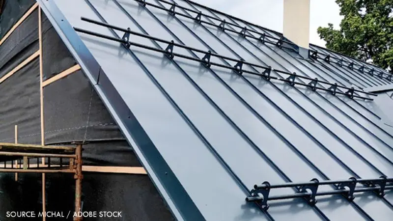
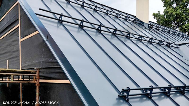
Snow Retention Systems: These create significant downslope drag loads, acting parallel to the roof slope and pulling heavily against the clamps.
Solar Arrays: These primarily introduce wind uplift loads that act perpendicularly, attempting to peel the attachments—and potentially the roof panels—away from the structural framing.
Service Walkways and Mechanical Units: These introduce concentrated downward service loads compounded by lateral drag and vibration forces.
Because these loads are dynamic, selecting a clamp involves matching the application’s specific mechanical demands with third-party tested holding strengths. Selection can never be standardized by guesswork; it must be treated as an engineered structural connection.
Chronology: The Evolution from Guesswork to Precision Engineering
The reliance on standing seam metal roofs has transformed dramatically over the past several decades.
The Early Decades: The Era of "Rule of Thumb" Construction
In the formative years of architectural metal roofing, attachments were frequently custom-fabricated on-site or adapted from unrelated mechanical fasteners. Installers relied on visual inspections and general rules of thumb to determine placement intervals. If a snow guard system "looked right," it was deemed complete. Little analytical thought was given to ultimate yield strengths, panel gauge thickness, or dynamic thermal cycling.
The Rise of Non-Penetrating Technology
As metal roofing grew in popularity due to its longevity and energy efficiency, the demand for rooftop accessories—particularly solar energy systems—skyrocketed. Punching holes through standing seams to mount these systems defeated the core waterproofing advantage of metal architecture. This drove the innovation of non-penetrating seam clamps, which rely on friction and mechanical interlock.
The Shift to Third-Party Testing and Standardization
Recognizing that field failures could compromise entire building envelopes, forward-thinking manufacturers began partnering with accredited laboratories. The industry transitioned from arbitrary installation habits to empirical data. Ultimate failure loads were tested, factors of safety were formally calculated, and load tables became the blueprint for installation layouts. Today, modern building science treats roof clamps not as mere accessories, but as engineered structural lifelines.
Supporting Data: Understanding Load Capacity and Safety Factors
The cornerstone of proper clamp specification is empirical data derived from accredited third-party laboratory testing.
Tested Load-to-Failure Data
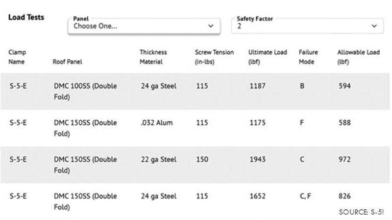
Every professional-grade clamp must possess a documented load-to-failure threshold specific to the exact roof panel profile, material, and gauge to which it will be attached. When manufacturers test these devices, they push them to the point of ultimate failure—whether that failure manifests as clamp slip, set-screw shear, or seam deformation.
The Critical Role of the Factor of Safety
Contractors and specifiers must look beyond the ultimate load to find the "allowable" load. This conversion is governed by a factor of safety (FS).
Generally, the industry benchmark mandates an FS of 2.0 or greater.
This means the allowable design load is set at precisely half of the ultimate tested failure load.
Depending on the critical nature of the application, building codes or engineers may adjust this factor, but designing without a verified safety factor strips the installation of its engineering validity.
Material Variables and Panel Mechanics
Panel material and thickness dramatically alter holding capacities. A clamp that performs exceptionally well on a 24-gauge steel panel may yield drastically different results on a softer 0.032-inch aluminum panel, zinc, or copper. Metallurgical compatibility is equally vital; pairing dissimilar metals without proper isolation can trigger galvanic corrosion, slowly eating away at the structural connection over time.
Official Perspectives: Expert Insights on Quality Assurance
Rob Haddock, CEO and founder of S-5! and an internationally recognized authority on metal roof architecture, emphasizes that quality assurance rests upon three non-negotiable pillars: engineered application, certified testing, and consistent manufacturing.
According to Haddock, navigating from raw load data to a physical layout requires meticulous preparation. Before contacting a manufacturer for layout assistance, contractors should compile a comprehensive project profile containing:
Project geographic location and local building code wind/snow parameters.
Specific roof manufacturer, profile name, and exact panel material/gauge.
The specific nature of the rooftop attachment (e.g., solar dead-load, rail-less solar, snow guards, conduit).
Desired layouts and system footprints.
"Moving from load data to layout demands more than a standard spacing rule," Haddock explains. "It requires tested performance data, project-specific details, and proper installation for the clamp system to perform as intended over the life of the roof."
Furthermore, Haddock highlights the importance of environmental considerations, which span two distinct realms:
In-Service Environmental Forces: The physical loads—such as thermal expansion, wind uplift, and gravity-driven drag loads—that the system must endure year after year.
Implications: Best Practices for Installation and Risk Mitigation
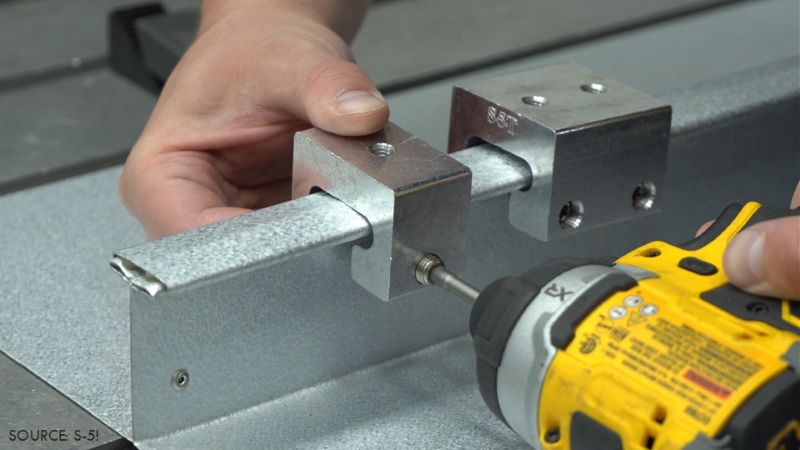
Even the most rigorously engineered clamp can fail if installation practices are flawed. Because these clamps secure attachments without penetrating the panels, proper torque is paramount.
The Dangers of Incorrect Torque
Over-Torquing: Applying excessive force with a driver tool can strip set screws, warp the clamp body, deform the underlying roof seam, or fracture the protective factory finish, opening the door to corrosion.
Under-Torquing: Failing to reach the manufacturer’s specified torque prevents the clamp from achieving its tested holding friction, risking slippage under load.
Installers must calibrate their driving tools precisely. To maintain quality control across large roofs, technicians do not necessarily need to verify every single fastener; standard protocol recommends checking roughly every 200 fasteners using a calibrated torque wrench to ensure consistent tension delivery.
Special Installation Protocols
Anti-Back-Out Features: Many modern clamps feature specialized mechanisms designed to resist the constant micro-vibrations caused by wind flutter or low-level seismic activity. Using incorrect installation methods can compromise these features.
Sequencing for Snow Retention: When installing multi-row snow retention systems, sequencing is vital. Crews must always install the uppermost row first and work their way down the slope. Stopping midway with only a lower row installed can lead to catastrophic system overload if an unexpected early-season storm strikes.
Warranty Protection: Manufacturers’ warranties are frequently contingent upon strict adherence to installation guidelines. Unapproved clamps, panel damage, or stray fastener penetrations can instantly invalidate a building’s weather-tightness or accessory warranty.
Conclusion
Roof clamps represent the intersection of micro-hardware and macro-structural engineering. By replacing guesswork with certified test data, respecting project-specific environmental loads, and adhering to strict installation torques and sequencing, the metal construction industry can ensure that rooftop attachments perform flawlessly over decades of service. When in doubt, building professionals are strongly urged to consult manufacturers, request physical samples, and secure engineered layouts before a single fastener is driven.