

Main Facts
Air Handling Units (AHUs) equipped with airflow tracking control for return fans represent a cornerstone of modern commercial and institutional HVAC design. However, when these systems operate—either intentionally or unintentionally—in a fully recirculating configuration, they become susceptible to a severe, highly nuanced operational failure mode known as the "AHU recirculating mode death spiral."
This complex mechanical phenomenon occurs under a precise set of operating conditions: the outdoor air (OA) and relief air (RA) dampers are fully closed, the return air (RA) damper is fully open, and the return fan attempts to control a return airflow setpoint that is reset to maintain a fixed offset from the measured supply airflow. When these variables align, the system enters an unstable feedback loop. One fan is driven to 100% capacity while the other bottoms out at minimum speed, creating a cascading failure that compromises building pressure relationships, zone cooling, dehumidification, and static pressure control.
While this failure mode can be triggered by deliberate programming errors in closed-loop configurations, it frequently manifests unintentionally due to poor commissioning handoffs, improper damper minimum position overrides, and cascading diagnostic failures by facility operations teams. This report examines a compelling multi-year case study at an active hospital facility, detailing how an improper override of an outdoor air damper minimum position plunged a critical AHU into a recurring recirculating death spiral, threatening indoor environmental quality and building pressurization.
Chronology
The Initial 2018 Incident: The Summer Static Pressure Failure
Several summers ago, facility engineering staff at an active hospital contacted Questions & Solutions Engineering regarding a persistent operational failure: the primary AHU serving multiple critical Variable Air Volume (VAV) zones could no longer maintain its supply air static pressure (SA-P) setpoint.
Upon initial inspection, commissioning engineers found the AHU operating in the precarious state illustrated in Figure 1. The return fan was locked at its minimum speed limit because its airflow measuring station (AFMS) was reading 1,556 CFM higher than the measured supply airflow—and a staggering 2,056 CFM above its active return airflow setpoint.
Because it was summer, the building automation system (BAS) had disabled the economizer, commanding the outdoor air and relief air dampers toward their minimum positions. A default minimum position of 10% was specified for the outdoor air damper by the original balance contractor. However, BAS trend logs revealed that this value had been subjected to an active software override, highlighted in purple within the control graphics.
When engineers released the override, they discovered that a Test and Balance (TAB) contractor had recently entered a default minimum position of 50% during routine optimization work. Upon querying the TAB provider, the engineering team confirmed that a 50% open position was indeed required to satisfy baseline minimum ventilation airflow requirements for the hospital spaces served.

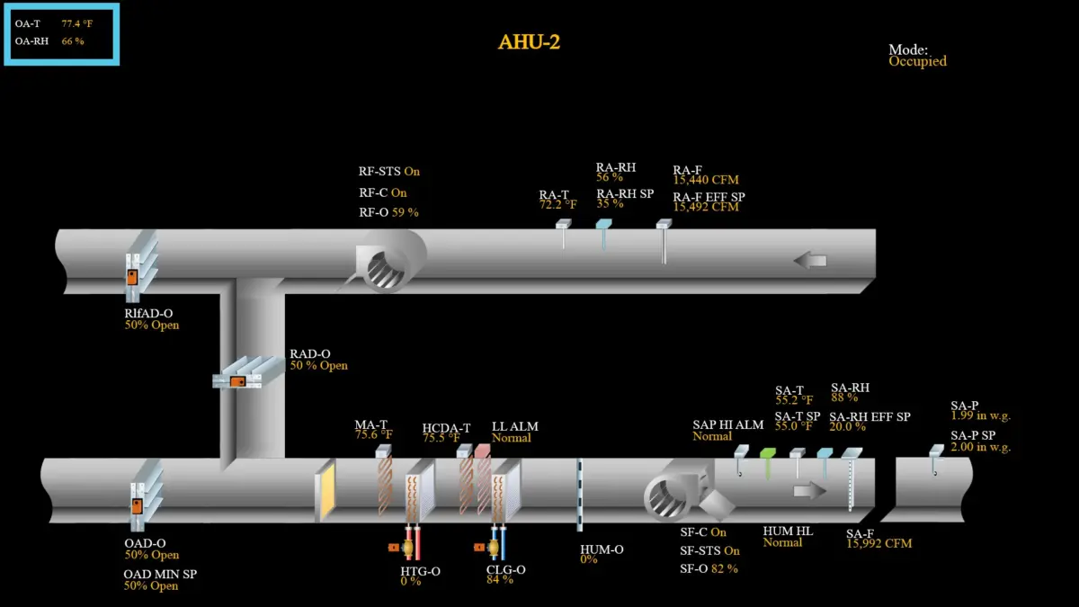
Once the appropriate 50% minimum position was restored to the outdoor air damper, the AHU rapidly self-stabilized, as shown in Figure 2. Supply air static pressure recovered immediately, downstream VAV boxes satisfied their airflow demands, and the return fan modulated smoothly to achieve its desired tracking setpoint. Commissioning engineers recommended a comprehensive cleaning and recalibration of both the supply and return airflow measuring stations to ensure long-term measurement fidelity.
Version 2.0: The Resurgence and Positive Pressurization Failure
Fast forward several summers. Facility renovations were executed on several zones served by this exact AHU. The architectural and mechanical design intent dictated that these renovated spaces maintain positive pressurization relative to adjacent hospital corridors and rooms to prevent contaminant migration.
At the conclusion of the renovation project, testing revealed that these positive space pressure requirements were failing. The spaces were starved of the supply airflow volumes requested by their terminal units.
Investigating the root cause, commissioning engineers once again found the AHU trapped in the exact configuration observed years prior: the outdoor air damper minimum position had been forced down to a 10% override.
When questioned, facility operations staff confessed that they had deliberately implemented the override weeks earlier. They reported that the AHU was utterly incapable of cooling and dehumidifying the facility spaces when the TAB-mandated 50% minimum outdoor air damper position was active.
With the TAB contractor onsite, the commissioning engineer connected remotely to the Building Automation System (BAS) via virtual desktop, maintaining a phone bridge with the technician at the air handler. The engineer released the minimum outdoor air damper setpoint override back to the validated 50% design position. The AHU settled smoothly into the operating conditions captured in Figure 3.
Supply air static pressure was instantly recovered as the return fan ramped up to share the system pressure drop. Increased airflow reached the downstream VAV terminals, and the positive pressure differentials across the newly renovated hospital spaces were successfully achieved.

Supporting Data and Technical Mechanics
To understand why this AHU repeatedly fell into the recirculating mode death spiral, one must examine the control sequence and the aerodynamic realities of opposing-blade dampers.
The Control Sequence and Damper Mechanics
The AHU operated under a conventional dual-fan tracking sequence:
- Supply Fan Control: Modulated dynamically to maintain supply air static pressure (SA-P) at its active setpoint (SA-P SP).
- Return Fan Control: Modulated to maintain return airflow (RA-F) at a dynamic setpoint (RA-F EFF SP) reset to track precisely 500 CFM below the real-time measured supply airflow (SA-F).
- Damper Operation: Outdoor air and relief air dampers tracked in unison, while the return air damper modulated inversely. A minimum position was established for the outdoor air damper to guarantee code-compliant outside air intake regardless of economizer status.
However, the AHU utilized opposed-blade dampers. Due to the non-linear flow characteristics of opposed-blade dampers, commanding them to a 10% open position leaves them mechanically near-closed. When combined with the low minimum position, the outdoor and relief air paths were effectively choked off.
The Physical Manifestation of the Death Spiral
With the outdoor and relief air paths restricted, the supply fan was forced to pull 100% of its intake air from the return ductwork. Consequently, the return airflow measuring station registered a flow rate artificially higher than the supply airflow.
Interpreting this false reading through the tracking logic, the return fan control loop systematically reduced fan speed until it bottomed out at its minimum RPM limit.
With the return fan idling at minimum speed and contributing little to system energy, the supply fan was forced to shoulder the entire pressure drop of both the supply and return duct networks single-handedly. Because standard supply fans in VAV systems are not sized to overcome the combined resistance of both distribution paths, the supply fan failed to achieve its static pressure setpoint. This resulted in starved VAV boxes, collapsed duct pressures, and lost space pressurization control.
The Chilled Water and Condensate Trap Failure
The drama did not end with damper override release. The moment the commissioning engineer restored the 50% minimum outdoor air damper position, the TAB provider onsite reported an extraordinary physical event: the condensate drain piping located directly beneath the cooling coil began "gushing" water onto the mechanical room floor drain.

For a condensate drain—housed within a negatively pressurized cabinet section of an operating air handler—to expel a deluge of standing water, a massive column of water must have accumulated inside the cooling coil drain pan. This represented an entire summer’s worth of trapped condensation.
The drainage system could not function while the AHU was trapped in the recirculating death spiral because the unit’s configuration generated extreme negative static pressure at that specific cabinet section, locking the condensate in place via atmospheric suction. The moment proper airflow and cabinet pressures were restored by lifting the damper override, the static pressure differential normalized, allowing the accumulated water to evacuate violently.
Further forensic review of the BAS trends (Figure 3) uncovered why facility staff had originally panicked and overridden the dampers: the cooling coil was underperforming. The supply air temperature setpoint could not be met.
Investigation into the chilled water plant revealed that the cooling coil was receiving entering water at 50°F instead of the specified 44°F. This thermal deficit cascaded into a secondary failure within the central chilled water distribution infrastructure. Once the chilled water supply temperature was corrected to 44°F, the AHU successfully delivered both the required thermal conditioning and the volumetric airflow demanded by the hospital spaces.
Official Responses and Stakeholder Actions
The resolution of these chronic failures required close coordination among multiple engineering and operational stakeholders:
- Commissioning Providers (Questions & Solutions Engineering): Diagnosed the root systemic flaws in the tracking control logic, identified the unauthorized damper overrides, and established remote-access protocols to coordinate real-time corrective actions with on-site technicians.
- Test and Balance (TAB) Contractors: Verified baseline minimum ventilation parameters, confirmed the necessity of the 50% outdoor air damper minimum position for code compliance, and assisted in real-time physical verification during the Version 2.0 remediation.
- Hospital Facility Operations Staff: Acknowledged the operational pressures that led to unauthorized damper overrides—specifically, attempting to compensate for unmitigated chilled water temperature deficiencies—and committed to adhering strictly to validated BAS setpoints moving forward.
- Mechanical Maintenance Teams: Initiated immediate corrective maintenance on the central chilled water plant to drop entering water temperatures from 50°F to the required 44°F design standard, resolving the underlying thermal capacity bottleneck.
Implications for HVAC Design and Commissioning
The multi-year operational saga of this hospital AHU underscores several critical takeaways for facility engineers, mechanical designers, and commissioning authorities:
- Beware the Interplay of Airflow Tracking and Minimum Dampers: Airflow tracking loops are inherently sensitive. When combined with tight minimum damper positions or opposed-blade damper nonlinearities, systems can inadvertently slide into fully recirculating states without explicit programming intent.
- The Danger of Symptomatic Overrides: Facility staff, under pressure from building occupants regarding thermal comfort or humidity, frequently apply software overrides (such as clamping outdoor air dampers to 10%) to mask upstream thermal failures. As demonstrated, this practice can induce secondary structural and mechanical failures, such as trapped condensate and loss of space pressurization.
- Holistic Troubleshooting: A drop in cooling coil performance is rarely isolated to damper positioning. In this case study, a thermal issue (50°F entering water) masqueraded as an airflow control problem, triggering a chain reaction of improper overrides that plunged the AHU into the recirculating mode death spiral.
- Maintenance of Airflow Measuring Stations: AFMS devices drift over time. Regular cleaning and recalibration are mandatory to ensure that tracking loops receive accurate real-time differential data.
The engineering community must remain vigilant against the AHU recirculating mode death spiral. As subsequent case studies in this series will demonstrate, this failure mechanism transcends specific control sequences, threatening complex HVAC systems across diverse architectural typologies unless properly diagnosed, commissioned, and maintained.
