

Main Facts
Modern commercial and institutional facilities rely heavily on complex Air Handling Units (AHUs) to maintain indoor air quality, thermal comfort, and precise building pressurization. However, a nuanced and frequently misunderstood operational vulnerability plagues systems that utilize airflow tracking to control return fans while operating in, or transitioning to, a fully recirculating configuration. This systemic flaw—commonly referred to in HVAC engineering circles as the AHU recirculating mode death spiral—occurs when outdoor air dampers and relief air dampers are fully closed, the return air damper is fully open, and the return fan attempts to maintain an isolated airflow set point.
Under these conditions, the return airflow set point is dynamically reset to maintain a specific offset from the measured supply airflow. When the AHU enters a fully recirculating damper configuration, the return airflow can no longer stably track its set point. Instead, the supply and return fans engage in an antagonistic control loop feedback cycle. This aerodynamic conflict eventually drives one fan to operate at maximum capacity while the other plummets to its minimum speed threshold, precipitating severe second-order operational anomalies, mechanical strain, variable frequency drive (VFD) trips, and, in extreme cases, catastrophic equipment degradation.

This technical crisis can manifest intentionally—such as during specific smoke evacuation modes or night-purge cycles—or unintentionally, triggered by sensor calibration drift, network latency, uncoordinated airflow-measuring stations, or inappropriate minimum outdoor air damper set points. This report explores the third installment of an ongoing diagnostic series, investigating a critical hospital installation where an AHU unexpectedly entered this death spiral during routine functional testing.
Chronology: The Anatomy of a Control System Collapse
The events unfolded during the commissioning and functional testing phase of a newly installed AHU serving a state-of-the-art healthcare facility. The unit was designed with a sophisticated control matrix meant to balance indoor air quality, ventilation compliance, and building pressure dynamics.

Initial Configuration and Baseline Operation
During March, under relatively cool ambient weather conditions, the AHU operated smoothly with the economizer enabled. The control architecture functioned as follows:
- Minimum Outdoor Air (MinOA-F): Actively controlled via a dedicated minimum outdoor air damper (MinOAD-O) to satisfy strict healthcare ventilation standards, measured using a duct-mounted airflow station.
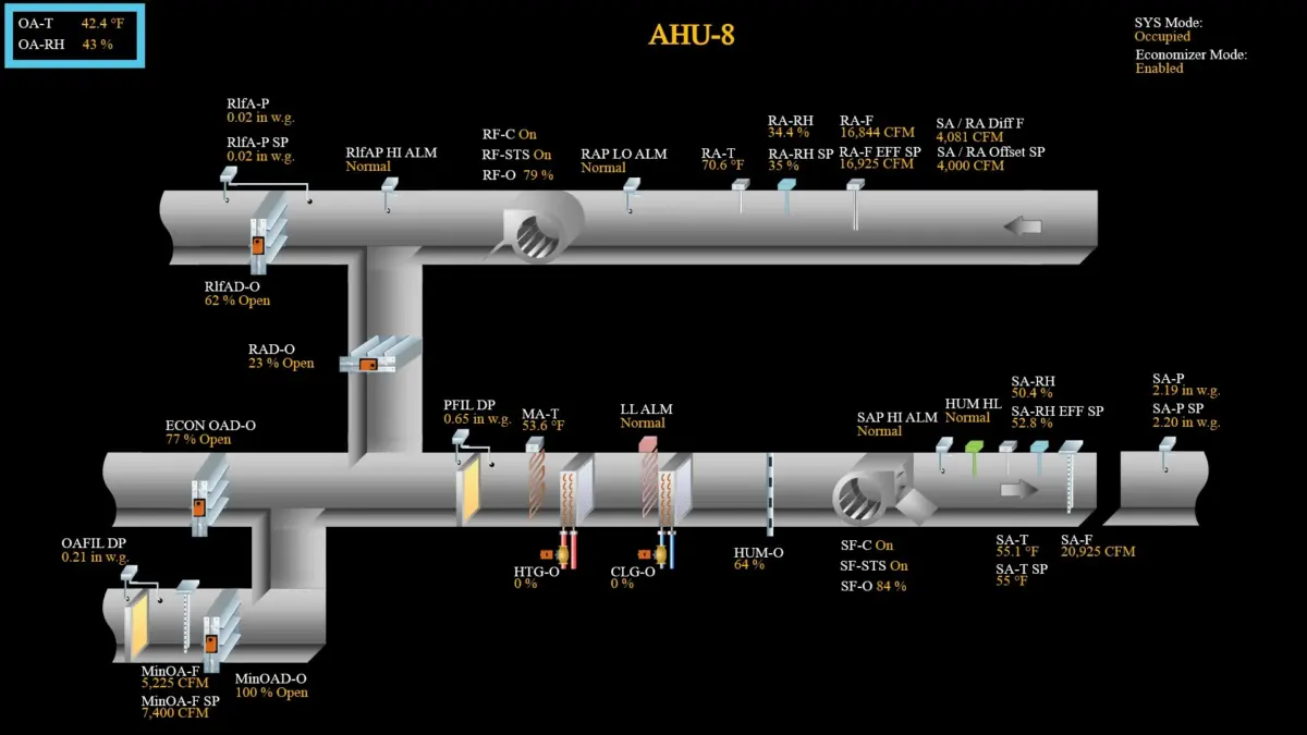
- Return Fan Control: Modulated to maintain return airflow (RA-F) at a dynamic set point (RA-F EFF SP), which continuously tracked a designated offset (SA/RA Offset SP) from the measured supply airflow (SA-F) to preserve building pressure balance.
- Relief Air Modulation: Regulated via a relief air damper to maintain a stable relief air pressure (RlfA-P) set point, ensuring air was never drawn backward into the building from the exhaust path.
- Economizer Loop: The return air damper (RAD-O) and economizer outdoor air damper (ECON OAD-O) modulated inversely in response to thermal cooling demands.
The Trigger: Disabling the Economizer
To test system resilience under minimum-outdoor-air requirements, engineers disabled the economizer. Theoretically, the sequence should have shifted the unit into a stable minimum-outdoor-air configuration. With measured outdoor airflow exceeding the mathematical differential between supply and return airflows, the relief damper should have cracked open slightly to bleed off excess return air.

Instead, a cascading systemic failure occurred within minutes:
- The VFD Trip: The return fan abruptly tripped on an unfamiliar VFD alarm. Due to Building Automation System (BAS) network latency, engineers could not instantly visualize the cascading mechanical inputs and outputs in real time.
- The Initial Damper Shift: Upon disabling the economizer, the return air damper drove fully open, the economizer outdoor air damper drove fully closed, and the relief air damper unexpectedly slammed shut. While unexpected, this initial closure was plausible due to complex external variables affecting relief plenum pressure, including ambient wind velocity, fluctuating building static pressures, and inherent damper resistance.
- Sensor Discrepancy and Control Drift: Conservation of mass dictates that with the relief damper closed, the outdoor airflow-measuring station should equal the exact mathematical difference between supply and return airflows. However, due to inevitable field-sensor tolerances, the measuring stations drifted out of alignment. The outdoor airflow station (MinOA-F) reported a value significantly higher than both the actual differential and its programmed set point (MinOA-F SP).
- The Positive Feedback Loop: Reacting to the falsely elevated airflow reading, the minimum outdoor air controller commanded the minimum outdoor air damper (MinOAD) to close. As this damper pinched down, the supply fan was forced to draw a higher volume of air from the return path.
- Fan Antagonism: The resulting surge in return airflow was detected by the return airflow station, prompting the return fan VFD to decelerate. This deceleration further starved the return path, pulling an even higher vacuum through the minimum outdoor air duct and forcing the MinOAD to close down further.
- The Death Spiral Apex: The supply fan ramped aggressively toward maximum speed to compensate for the sluggish return fan, while the MinOAD and return fan applied mechanical "brakes." This destructive tug-of-war continued until the MinOAD was nearly sealed shut, at which point its local sensor finally registered agreement with the set point. By this juncture, the return fan had bottomed out at minimum speed, while the supply fan operated near maximum capacity. The return fan, overwhelmed by air being forced backward through its housing, effectively turned into an air turbine, triggering a protective VFD fault shutdown.
Supporting Data & Technical Observations
Engineering diagnostics revealed that the root cause of the hospital AHU failure was not a singular mechanical defect, but rather a vulnerability embedded within the control logic’s unshielded sequencing.

Comparative Operational States
- Normal Economizer Mode (Figure 1): The system balanced ventilation requirements across dual outdoor air paths, maintaining stable static pressures despite minor localized sensor deviations.
- Theoretical Minimum OA Mode (Figure 2): Designed parameters indicated steady-state operation where the relief damper actively bled excess volume. Actual field execution deviated completely from this model due to uncoordinated sensor inputs.
- Initial Disturbance State (Figure 3): The sudden closure of the relief damper introduced pressure instabilities. Because the airflow-measuring stations (MinOA-F, SA-F, RA-F) lacked a calibrated baseline cross-check, the control loop trusted erroneous sensor data.
- Terminal Failure State (Figure 4): The system locked into a fully recirculating loop. The supply fan saturated at 100% capacity, while the return fan stalled at minimum speed, creating a dangerous pressure differential across the internal filtration and coil sections.
A Related Anomaly
Earlier on the day of testing, engineers observed a mirrored failure on a separate AHU within the same facility. Upon disabling the economizer, the minimum outdoor air damper drove fully open but failed to satisfy its airflow set point (Figure 5). In this secondary instance, while the sensor readings remained relatively synchronized, the return air path offered insufficient flow resistance. The system lacked the capability to throttle the recirculated air path dynamically, preventing the unit from pulling adequate fresh air through the minimum outdoor air intake.
Official Responses and Engineering Remedies
Faced with these recurring vulnerabilities—characterized by uncoordinated airflow-measuring stations, vulnerable relief damper responses, and the absence of operational guardrails—the commissioning team formulated a comprehensive design modification.

The proposed remediation strategy focused on fortifying the minimum outdoor airflow control loop sequencing. By introducing programmatic guardrails—most notably a MinOAD low-limit floor (illustrated in Figure 6)—the control logic was updated to prevent the system from commanding dampers into a fully recirculating configuration under sensor drift scenarios.
The design engineer accepted the proposed sequence modifications. Subsequent re-testing proved the updated logic entirely viable, rendering the AHUs resilient against unexpected relief damper closures and transient sensor inaccuracies. The system could now successfully arbitrate conflicting airflow measurements without allowing the supply and return fans to enter a destructive antagonistic feedback loop.

Implications for HVAC Design and Facilities Management
The implications of the AHU recirculating mode death spiral extend far beyond a single hospital installation. Modern energy codes and ventilation standards (such as ASHRAE Standard 62.1) mandate rigorous outdoor air tracking and minimum ventilation verification. However, engineers and controls contractors frequently overlook the complex dynamic interactions between supply, return, and relief subsystems when control loops interact under constrained damper positions.
Key Takeaways for Industry Professionals:
- Sensor Calibration and Redundancy: Airflow-measuring stations are notoriously susceptible to duct turbulence, approach-distance limitations, and dust accumulation. Relying exclusively on uncalibrated differential pressure or thermal dispersion stations to drive critical damper actuators invites system instability.
- Control Loop Guardrails: Sequences of operation must incorporate robust software logic—such as minimum position limits, validation cross-checks, and maximum offset constraints—to prevent control loops from chasing phantom errors into a fully recirculating death spiral.
- Commissioning Rigor: Functional performance testing must deliberately simulate worst-case scenarios, including economizer disablement, fluctuating building pressures, and simulated sensor drift, to verify that safety interlocks protect mechanical assets like return fans from turbine-effect failures.
As buildings grow more airtight and ventilation controls become increasingly automated, anticipating the unintended consequences of interacting control loops remains paramount. By acknowledging vulnerabilities like the AHU death spiral and implementing proactive sequence guardrails, engineers can ensure that high-efficiency HVAC systems deliver both indoor air quality and mechanical longevity.
